A/C Manifold Gauge Set for Air Conditioning System Testing
-
Code:8425
-
Weight:2.892 Kgs
Overview:
✔ Manifold gauge set for testing and diagnosing automotive air conditioning systems
✔ Supplied with high-pressure hose, low-pressure hose and service connection hose
✔ Gauges mounted in a protective aluminium manifold body
✔ Integrated shut-off valves for both high- and low-pressure sides
✔ Suitable for R12 and R134a systems and can also be used as a replacement gauge set for service machines
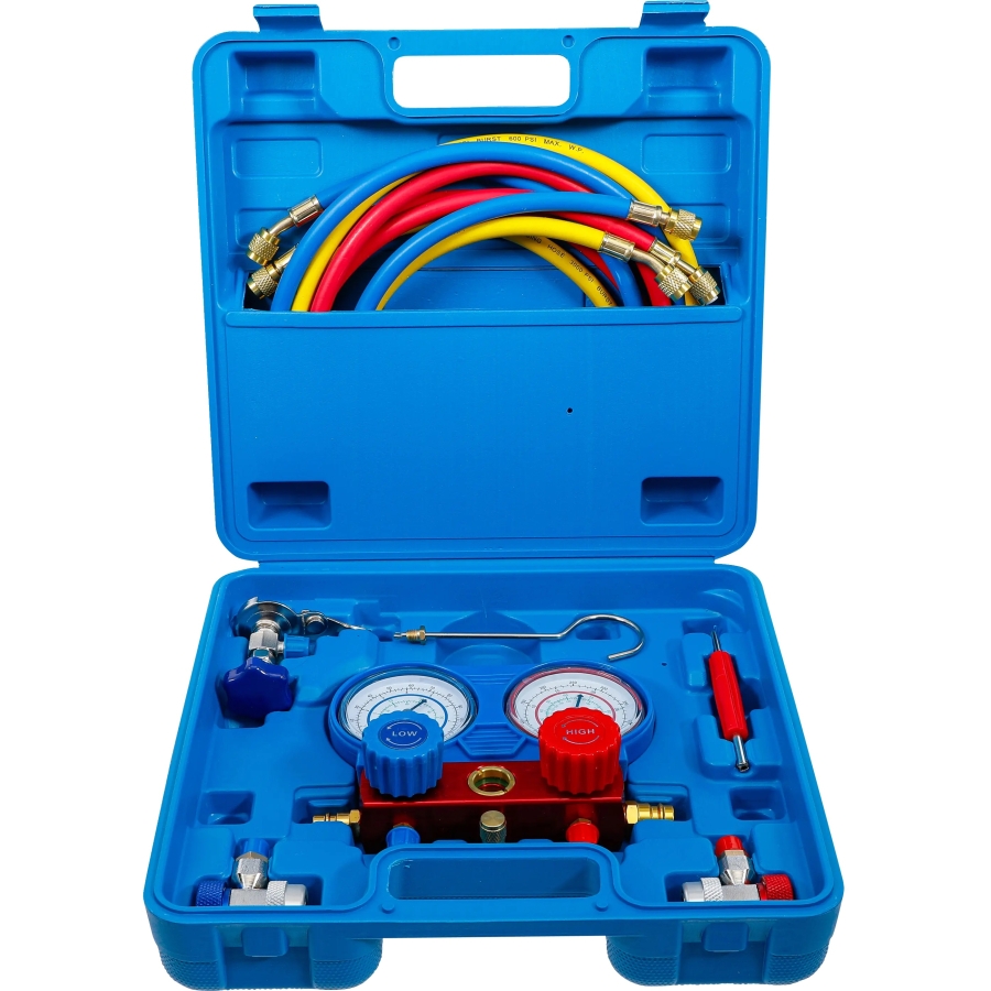
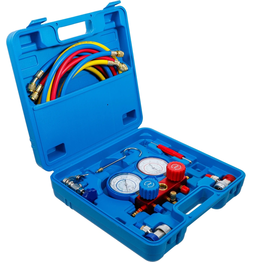
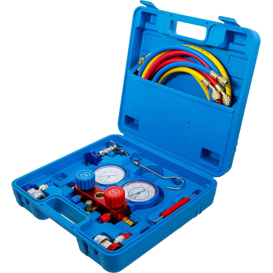
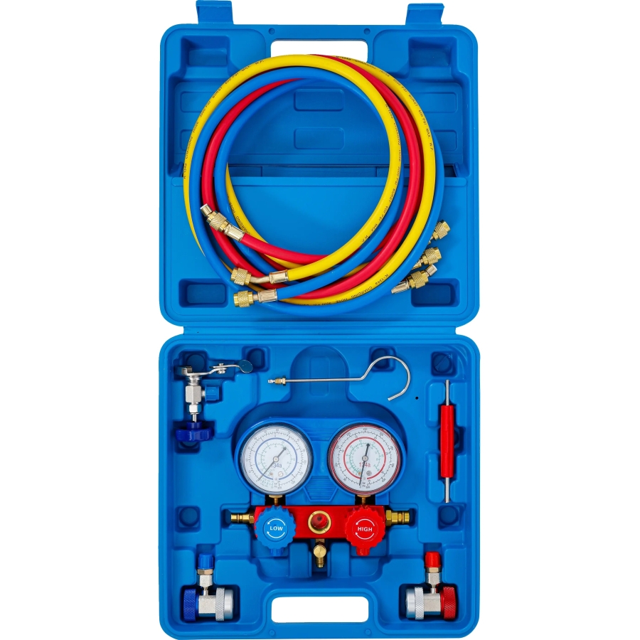
This manifold gauge set is designed for testing, servicing and diagnosing automotive air conditioning systems. It is supplied with a high-pressure hose, a low-pressure hose and an additional connection hose for linking to a service unit.
The pressure gauges are mounted in a robust aluminium manifold body for protection during workshop use. The manifold is fitted with integrated shut-off valves for the high-pressure and low-pressure sides, allowing controlled operation during system testing and service work.
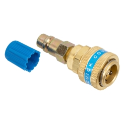
When the quick couplings on the pressure hoses are not in use, they can be attached to the blind ports on the sides of the manifold to protect the couplings. The unit is also fitted with a hanging hook for convenient positioning during use.
This gauge set is suitable for refrigerants R12 and R134a. It can be used as an ideal replacement for defective gauges on A/C service machines, but is also suitable for standalone diagnosis without a service station.
Technical Data
- Hose length: 1.5 m
- Suitable for refrigerants: R12 and R134a
Low-pressure gauge scale:
- 0 to 24 bar
- 0 to 350 PSI
- Vacuum scale: 10 to 30 in Hg
- Temperature scale: -40 to 37°C
High-pressure gauge scale:
- 0 to 34 bar
- 0 to 500 PSI
- Temperature scale: -10 to 88°C
- Temperature scale in °F: 0 to 190°F
Features
- Gauges mounted in protective aluminium manifold body
- Shut-off valves for high- and low-pressure circuits integrated into the manifold
- Side blind ports for storing quick couplings when not in use
- Hanging hook for workshop use and easier handling
- Suitable for diagnostics, testing and A/C service work
Scope of Delivery
- 1 x A/C manifold gauge set
- 1 x high-pressure hose
- 1 x low-pressure hose
- 1 x connection hose for service unit
Functions
- Connect one end of the low-pressure hose (blue) to the low-pressure port (blue) and the other end to the blue low-pressure quick coupler.
- Connect one end of the high-pressure hose (red) to the high-pressure port (red) and the other end to the red high-pressure quick coupler.
- The valves integrated into the high- and low-pressure couplers control the flow to the pressure gauges. Close both coupler valves by turning them counterclockwise.
- The red high-pressure gauge is connected to the line from the compressor outlet. On R134a air conditioning systems, the red high-pressure coupler is standardized and will not fit the blue low-pressure service port on the vehicle.
- The blue low-pressure gauge is connected to the line from the compressor inlet. On R134a air conditioning systems, the blue low-pressure coupler is standardized and will not fit the red high-pressure service port on the vehicle.
- The high- and low-pressure valves on the manifold control the refrigerant flow to and from the yellow service hose. If no service unit is connected, both manifold valves must be closed by turning them clockwise before connecting the gauge set to the vehicle.
- The sight glass allows visual inspection of the refrigerant condition.
- The yellow service hose is used to connect the manifold gauge set to a refrigerant recovery or service unit.
- When used with a service unit, the yellow hose is required for evacuating and recharging R134a air conditioning systems.
- General A/C service instructions should be taken from the service unit manual. Specific procedures for individual systems and vehicle models should always be taken from the vehicle manufacturer’s A/C service documentation.
Operation
Note: The following abbreviations are used in these instructions:
- HP = High Pressure
- LP = Low Pressure
- CW = Clockwise
- CCW = Counterclockwise
Note: Procedures such as charging refrigerant and adding compressor oil/lubricant are not covered in these instructions.
Pressure Test
Preparation
- Close the high-pressure and low-pressure manifold valves by turning them clockwise.
- Close both coupler valves by turning them counterclockwise.
Connecting the Hoses
- Connect one end of the blue hose to the low-pressure hose port and the other end to the blue coupler.
- Connect one end of the red hose to the high-pressure hose port and the other end to the red coupler.
- Connect one end of the yellow hose to the yellow charging/service port and the other end to the service unit.
Connecting the Couplers
- Attach the blue coupler to the low-pressure service port of the vehicle’s A/C system.
- Attach the red coupler to the high-pressure service port of the vehicle’s A/C system.
Performing the Test
- Start the vehicle and allow it to reach normal operating temperature.
- Switch on the air conditioning system.
- Open both coupler valves by turning them clockwise.
- Read the pressure values on both gauges and compare them with the manufacturer’s specified values.
After the Test
- Switch off the air conditioning system.
- Close both coupler valves by turning them counterclockwise.
- Disconnect both couplers from the A/C system by pulling up the knurled release ring on each coupler.
- Reconnect the couplers to their respective dummy ports or storage fittings.