Digital Voltage Tester 12–690V LCD
-
Code:40110
-
Weight:0.300 Kgs
Overview:
✔ Professional digital voltage tester for AC and DC measurements
✔ LCD display with voltage measurement range from 12–690V
✔ LED voltage indication with six predefined voltage levels
✔ Continuity tester with acoustic and visual indication
✔ Single-pole voltage detection and phase rotation testing
✔ Positive/negative polarity detection via LED indicator
✔ IP65 protection rating for workshop environments
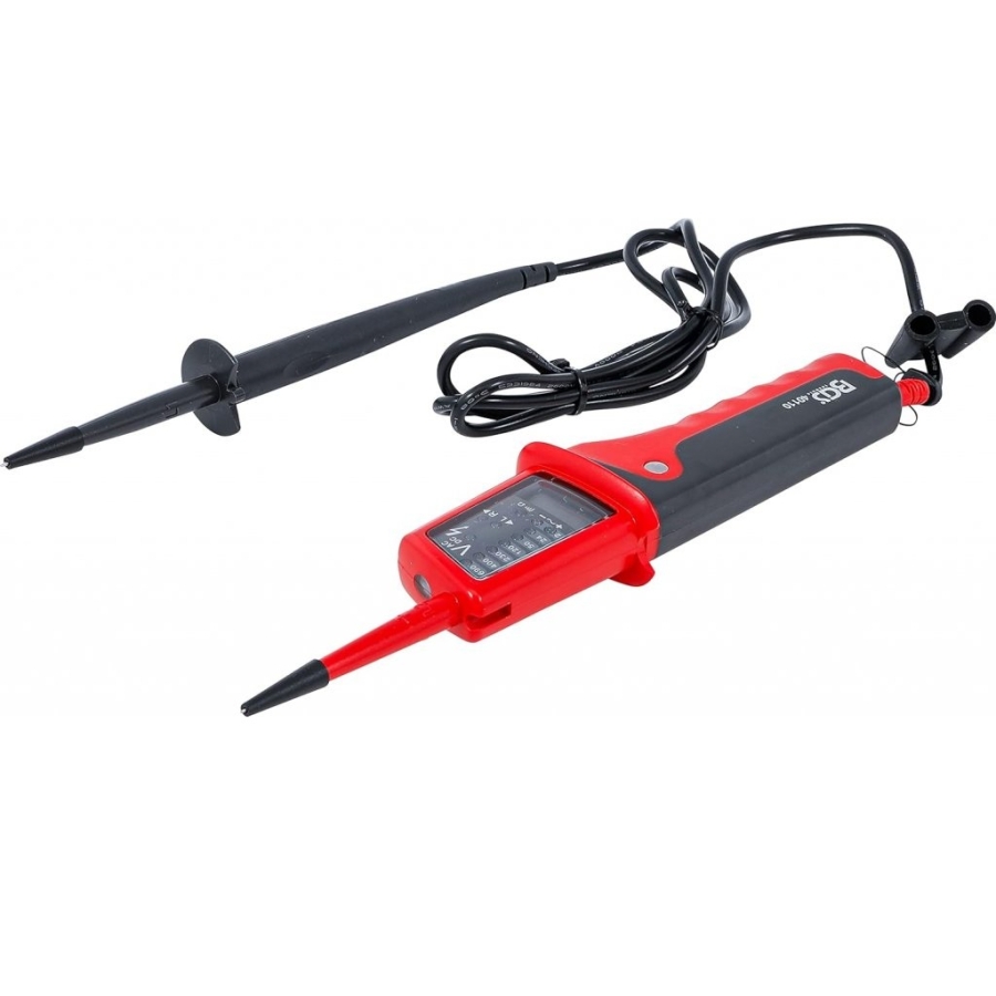
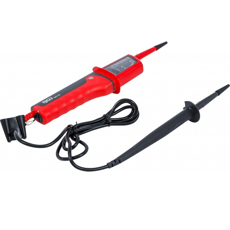
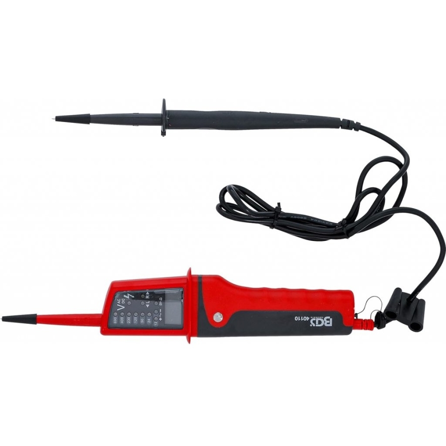
The Digital Voltage Tester 12–690V LCD is a professional measuring instrument designed for safe and precise testing of electrical systems and circuits. Suitable for both AC and DC voltage measurement, the device combines a clear LCD display with rapid LED indication for quick visual verification.
The tester features continuity testing with both audible and visual alerts, phase rotation testing, polarity detection, and single-pole voltage detection. Automatic voltage recognition simplifies operation and reduces setup time.
Its robust IP65-rated construction and integrated battery monitoring function make it suitable for professional workshops, maintenance work, automotive diagnostics, and electrical service applications.
Technical Specifications
- LCD voltage display range: 12–690V AC/DC
- LCD measurement accuracy: ±3% + 8 digits
- LED voltage indication:
- 12V
- 24V
- 50V
- 120V
- 230V
- 400V
- 690V
- Voltage detection: Automatic
- Acoustic signal: AC/DC voltage indication
- Polarity detection: Full range positive/negative detection
- LED response time: <0.1 sec
- Frequency range: 0–400 Hz
- Peak current:
- <0.3A
- <3.5mA after 5 seconds
- Operating time: 30 sec
- Recovery time: 10 min
- Automatic power-on: <12V AC/DC
Single-Pole Voltage Detection
- Voltage range: 100–690V AC
- Frequency range: 50–400 Hz
Continuity Test
- Measuring range: 0–400 kΩ
- Indication: Visual and acoustic
Phase Rotation Test
- Voltage range: 100–690V
- Frequency range: 45–65 Hz
Additional Specifications
- Overvoltage protection: 690V AC/DC
- Protection class: IP65
- Battery test function: Yes
- Power supply: 2 × 1.5V LR03 batteries
- Dimensions: 255 × 75 × 28 mm
- Weight: 210 g
Applications
Suitable for:
- Automotive electrical diagnostics
- Electrical maintenance and testing
- Workshop applications
- Voltage and continuity verification
- Professional service environments
Voltage Test
- Always hold the test probes by the handles behind the finger guards. Follow all safety instructions carefully.
- An audible signal will sound when AC voltage or negative DC voltage is detected.
- The maximum operating time is 30 seconds. After this period, wait 10 minutes before performing another test.
- Connect the test probes to the voltage source while observing the probe polarity. Probe L2 is the positive test probe and L1 is the negative test probe.
- For AC voltage, the measured value is displayed on both the LED indicators and the LCD display. The + and − LEDs will illuminate and the buzzer will sound.
- For DC voltage, connect test probe L2 to the positive terminal and L1 to the negative terminal. The voltage value will be displayed on both the LED indicators and LCD display. The positive LED (10) will illuminate. If the polarity is reversed, the buzzer will sound and the negative LED (11) will illuminate.
AC Voltage Test – Single-Pole Voltage Detection
Perform a function test before carrying out this test.
This device can be used as a single-pole voltage detector when batteries are installed.
The single-pole test is intended only for a quick check. The circuit must always be retested for voltage presence using the two-pole measurement method.
- Connect test probe L2 to the voltage source and keep your finger on the contact electrode.
- If an AC voltage above 100 V is present, the LED will illuminate and the buzzer will sound.
Note: Single-pole testing may be negatively affected by unfavorable conditions such as electrostatic fields, high-quality insulation, or similar factors.
Continuity Test
Continuity testing is only possible when batteries are installed and in good condition.
Ensure that the circuit to be tested is not energized.
- Connect test probes L1 and L2 to the circuit.
- The continuity LED will illuminate and the buzzer will sound.
The device indicates continuity at resistance values below 400 kΩ.