Glow Plug Removal and Thread Repair Kit for Audi and VW, M10×1, 28-Piece
-
Code:8722
-
Weight:4.220 Kgs
Overview:
✔ For drilling out damaged or broken glow plugs without removing the cylinder head
✔ Repairs M10×1 glow plug threads using M12×1 threaded inserts
✔ Guide sleeves ensure the correct drilling angle and depth
✔ Includes tools for extracting the glow plug electrode
✔ Enables cleaning of the glow plug and electrode bores
✔ Suitable for selected Audi and VW 2.5, 2.7 and 3.0 V6 TDI engines

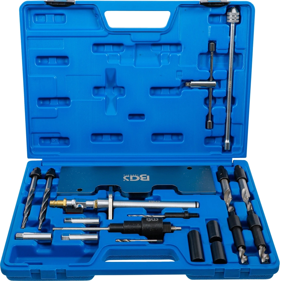
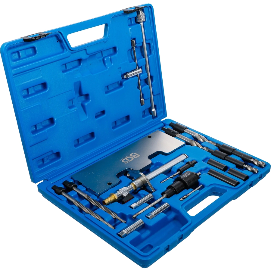
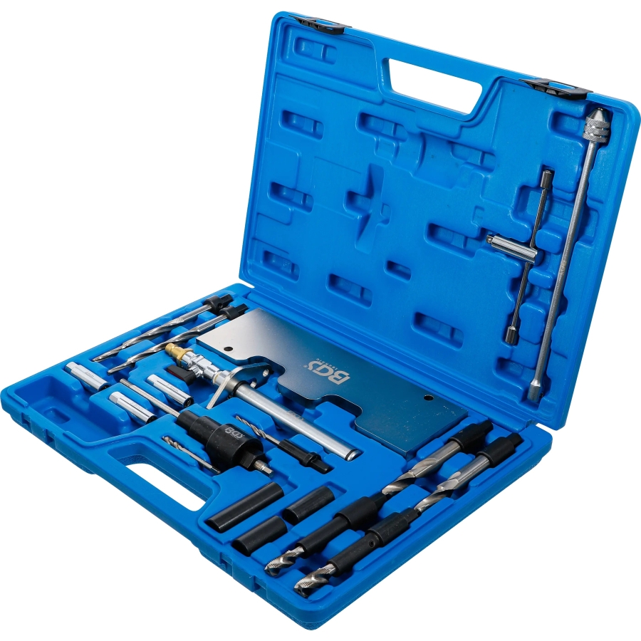
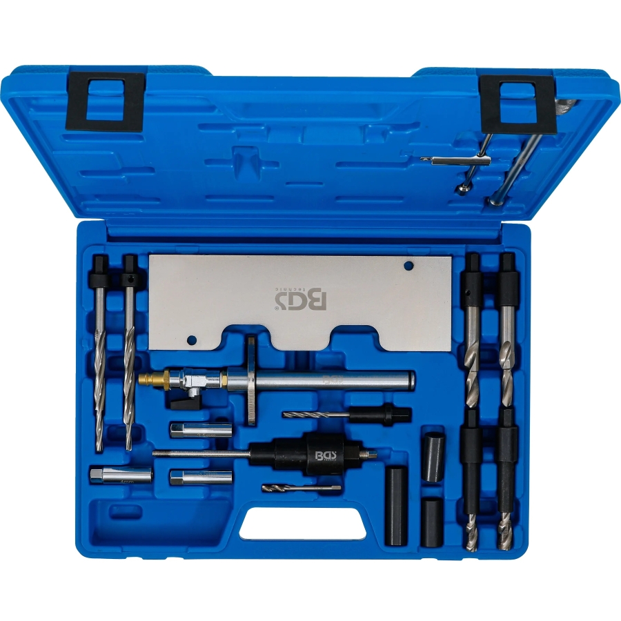
This 28-piece repair kit enables damaged or broken glow plugs to be drilled out quickly and professionally without removing the cylinder head.
After extraction, the glow plug thread can be recut or repaired using the included threaded inserts. The tools also allow the glow plug bore and electrode opening to be cleaned before installing a new glow plug.
Accurate and Controlled Drilling
The included guide sleeves ensure that the correct drilling angle and depth are maintained. This supports accurate tool guidance and reduces the risk of damaging the cylinder head during drilling and thread repair.
The cover plate protects the intake ports, while the compressed-air adapter allows air to be supplied through the injector bore to help prevent loosened particles from remaining in the combustion chamber.
Compatible Vehicles and Engines
Suitable for M10×1 glow plug thread bores in selected Audi and VW vehicles, including the VW Passat and models equipped with 2.5, 2.7 and 3.0 V6 TDI engines.
Compatible engine codes: AFB, AKE, AKN, ASB, AYM, BAU, BCZ, BDG, BDH, BFC, BKN, BKS, BMK, BNG, BSG, BUG, BUN
Scope of Delivery
- 1 × cover plate for the intake ports
- 1 × compressed-air adapter for the injector bore
- 1 × drill, 9.1 mm, for M10×1
- 1 × drill, 11.1 mm, for M12×1
- 1 × tap with guide sleeve for M10×1 threads
- 1 × tap with guide sleeve for M12×1 threads
- 10 × threaded inserts, internal thread M10×1 and external thread M12×1
- 1 × tap, M6×1.25
- 1 × extraction tool
- 1 × reamer, 4.8 mm, short
- 1 × reamer, 4.8 mm, long
- 1 × reamer, 5.8 mm, long
- 1 × guide sleeve, outside diameter 17.5 mm, length 38 mm, inside diameter 9 mm
- 1 × guide sleeve, outside diameter 17.5 mm, length 38 mm, inside diameter 13 mm
- 1 × guide sleeve, outside diameter 17.5 mm, length 63 mm, inside diameter 13 mm
- 1 × tap holder, 2.4–5.5 mm, length 240 mm, with 6.3 mm (1/4") drive
- 1 × extractor electrode, 2.5 mm
- 1 × extractor electrode, 3.5 mm
- 1 × extractor electrode, 4 mm
Drilling Out a Broken Glow Plug and Restoring the Thread
- Remove all components necessary to access the glow plug and injector.
- Mount the cover plate to the intake manifold using the original screws.
- Make sure the piston of the cylinder being repaired is at Top Dead Center (TDC).
- Remove the injector from the cylinder being repaired.
- Install the injector bore compressed-air adapter in the injector bore.
Caution: Secure the crankshaft against rotation. Connect the adapter to a compressed-air supply and open the valve. - Using the appropriate electrode removal tool, shear off the electrical connection/electrode by turning the tool in the specified direction.
- Remove the broken centre electrode and hexagonal section from the glow plug bore.
- Visually inspect where the remaining centre electrode has broken:
- Broken at the upper connection: Remove the remaining electrode using the electrode removal tool, then continue with the drilling procedure.
- Broken inside the glow plug body: The glow plug body can be removed directly using the core drill. Continue with the drilling procedure.
- Broken in the middle: Remove the remaining centre electrode using the cutter and continue with the following steps.
- Insert the appropriate guide sleeve into the glow plug bore as far as it will go.
- Lubricate the cutter with oil and machine out the centre electrode at 500 rpm until the cutter stop rests against the guide sleeve.
- Replace the guide sleeve with the guide sleeve required for the next machining operation.
- Lubricate the cutter again and continue machining at 500 rpm until the cutter stop once again rests against the guide sleeve.
- Lubricate the drill, insert it into the guide sleeve and drill out the glow plug at 500 rpm, applying only very light pressure.
Note: Remove swarf periodically using compressed air. Wear safety glasses. The drilling operation is complete when the shoulder of the drill drive rests against the edge of the guide sleeve. - Remove the drill and guide sleeve. Use compressed air to remove all swarf and contamination from the glow plug bore.
- Lubricate the tap, secure it in the tool holder and manually cut a thread approximately 5 mm deep into the remaining glow plug body.
- Screw the spindle of the extraction tool into the newly cut thread.
- Open the valve on the injector bore compressed-air adapter.
- Turn the 19 mm hexagon on the extraction tool to pull the remaining glow plug body out of the cylinder head.
- Insert the appropriate guide sleeve into the glow plug bore as far as it will go.
- Apply alcohol to the M10 × 1.0 tap and recut the glow plug thread by hand. Continue until the tool stop rests against the guide sleeve.
During this operation, the injector bore compressed-air adapter must remain connected to the compressed-air supply with the valve open. This prevents swarf from entering the combustion chamber. - Insert the guide sleeve for cleaning the glow plug channel as far as it will go.
- Use the new glow plug to determine the correct reamer for the glow plug channel.
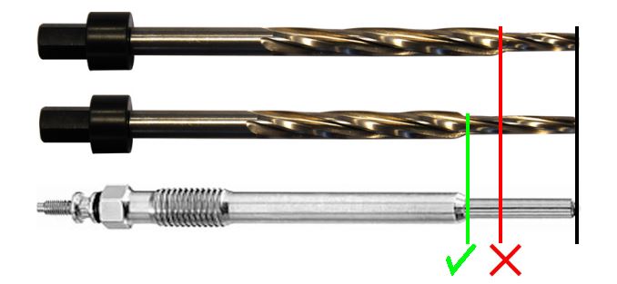
- Apply alcohol to the appropriate reamer, insert it through the guide sleeve and clean the glow plug channel at 500 rpm.
During this operation, the injector bore compressed-air adapter must remain connected to the compressed-air supply with the valve open to prevent swarf from entering the combustion chamber.
Repairing the Glow Plug Thread Using a Thread Insert
- Insert the appropriate guide sleeve into the glow plug bore as far as it will go.
- During the following operations, secure the crankshaft against rotation. Install the injector bore compressed-air adapter, connect it to a compressed-air supply and open the valve.
Caution: The compressed air forces machining swarf out of the bore and prevents it from entering the combustion chamber. Always wear safety glasses. - Apply alcohol to the drill, insert it through the guide sleeve and drill out the damaged thread at 500 rpm, applying only very light pressure. Continue until the shoulder of the drill drive rests against the edge of the guide sleeve.
- Remove the drill and clear away any accumulated swarf.
- Apply alcohol to the M12 × 1 tap and cut the new thread into the cylinder head by hand. Continue until the shoulder of the tap drive rests against the edge of the guide sleeve.
- Unscrew and remove the tap. Remove any remaining swarf and then remove the injector bore compressed-air adapter.
- Screw the repair thread insert together with the new glow plug into the cylinder head.
Caution: Observe the specified tightening torque for the glow plug.