Vacuum & Fuel Pump Tester
-
Code:117913
-
Weight:0.749 Kgs
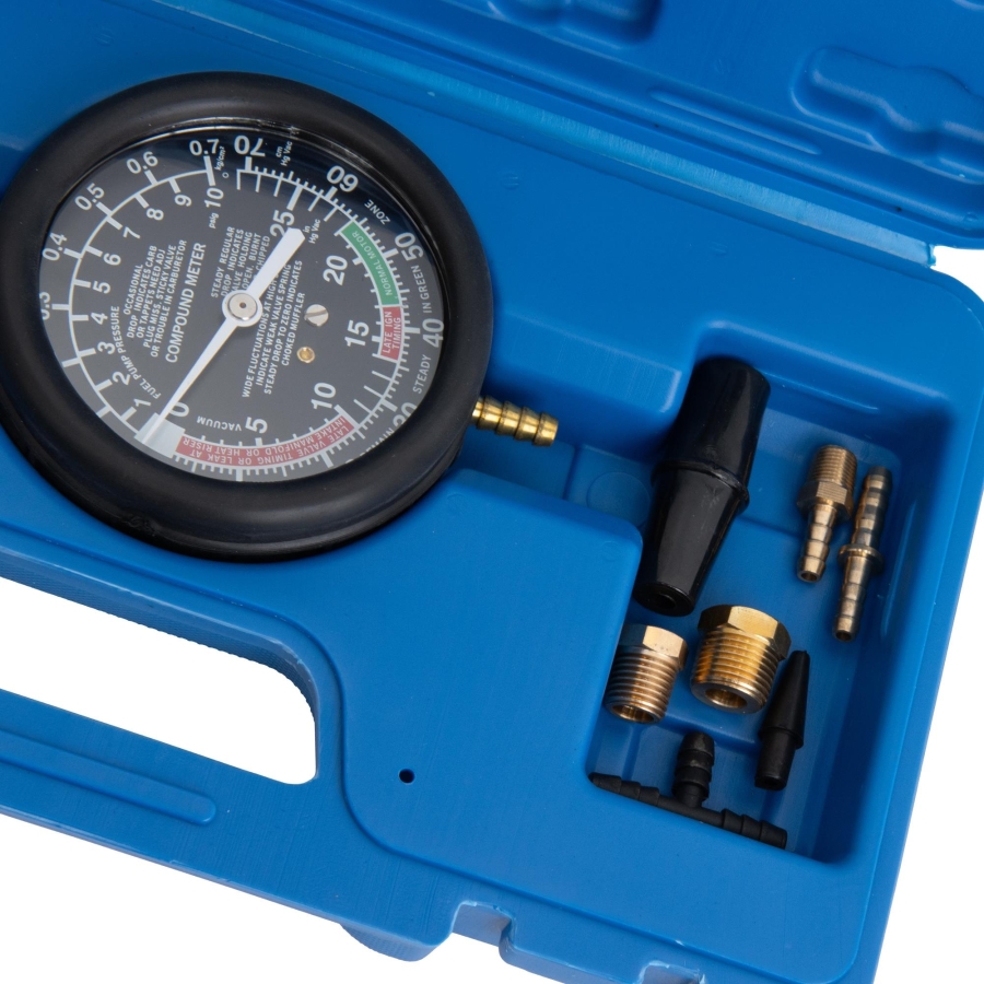
Professional vacuum and fuel pump tester for leak detection in fuel lines, intake systems, and mechanical fuel pumps. Features Ø89 mm pressure/vacuum gauge, flexible hose, and adapter.

Leak Detection and System Testing
This vacuum and fuel pump tester is designed for checking leaks in fuel lines, throttle bodies, intake manifolds, vacuum hoses, and exhaust/intake valves. It is ideal for inspecting mechanical fuel pumps and fuel delivery systems for proper operation.
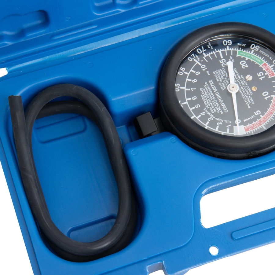
Accurate Pressure and Vacuum Measurement
Equipped with a pressure/vacuum gauge Ø89 mm with hanging hook and rubber cover, the tester allows precise monitoring during leak and system tests.
-
Vacuum range: 0–28 in Hg (0–70 cm Hg)
-
Pressure range: 0–0.7 kg/cm² (0–10 psig)
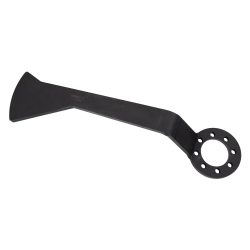
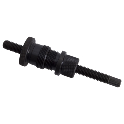
Flexible Hose and Adapter
The set includes a flexible hose and adapter, making it easier to reach difficult areas and connect to various system ports. This ensures accurate readings and reliable testing results.
Professional Workshop Solution
This tool is suitable for professional workshops, service technicians, and automotive specialists, providing an efficient and reliable method to detect leaks and verify system integrity.
Vacuum Testing – Engine
-
Use the supplied adapters to connect the gauge hose as close as possible to the intake manifold. Ensure the hose is not kinked.
-
For engines with dual intake manifolds, test each manifold separately.
-
-
Start the engine and adjust idle speed if necessary for a stable reading.
-
If the needle stabilizes between 17 and 22 inHg, the engine is in good condition.
-
If the gauge drops to about 4 inHg, this indicates a leaking valve.
-
If the needle steadily falls, it may indicate insufficient valve clearance or a burned valve.
-
If the needle pulses rapidly when revving, valve springs may be weak.
-
If the needle pulses at idle but stabilizes when revving, valve guides may be worn or clearance too large.
-
If the needle slowly returns after revving, this may indicate a clogged exhaust system.
-
If the gauge shows less than 10 inHg, engine timing may be incorrect.
-
Throttle check: Close the throttle and crank the engine. The gauge should quickly rise to 22 inHg. If it remains at 3–6 inHg, the throttle may not be fully closed or the intake manifold has a leak.
-
Note: Gauge readings vary with altitude. Example: at sea level ~19.5 inHg; every 305 m elevation reduces the reading by 1 inHg. At 610 m the reading would be ~17.5 inHg.
Vacuum Testing – Mechanical Fuel Pump
-
Disconnect the fuel line from the pump and seal it to prevent fuel leakage.
-
Connect the gauge to the pump inlet.
-
Start the engine. A reading of ~10 inHg indicates the pump is in good condition.
Pressure Testing – Mechanical Fuel Pump
-
Disconnect the fuel line from the pump outlet.
-
Connect the gauge to the outlet.
-
Start the engine; the fuel should be sufficient for ~2 minutes of operation.
-
Compare the gauge reading with manufacturer specifications.
-
After shutting down, the pressure should remain stable for several minutes. If it drops quickly, check the pump diaphragm and seals for leakage.
Carburetor Testing
-
Ensure spark plugs are in good condition, ignition timing and valve clearance are correct.
-
Connect the gauge hose to the intake manifold.
-
Start the engine and warm it to operating temperature.
-
At idle, the gauge should read 17–22 inHg.
-
If the needle varies between 14–22 inHg, carburetor adjustment is required.
-
-
Adjust the carburetor:
-
Idle mixture: Adjust until the highest stable reading is reached.
-
Higher RPM adjustment: Increase engine speed to 2000–2500 RPM and adjust mixture for maximum stable reading.
-
High/low RPM carburetors: Adjust idle first.
-
-
Note: Worn, clogged, or incorrect jets may prevent optimal adjustment.
Gauge Zero Adjustment
-
During transport or other conditions, the gauge needle may not read zero. To reset:
-
Remove the rubber cover by pulling forward and down over the connection.
-
Remove the plastic glass using a flat screwdriver, leveraging the slots on the edge.
-
Turn the adjustment screw in the direction needed to correct the needle.
-
Reinstall the plastic glass and rubber cover.