Vacuum & Pressure Pump Kit with Gauge | Brake Bleeder & Diagnostic Tool
-
Code:117930
-
Weight:1.720 Kgs
Overview:
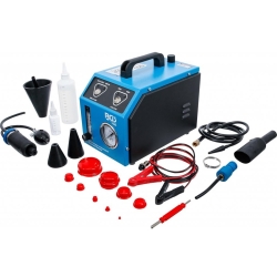
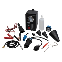
✔ Multifunctional vacuum and pressure pump kit
✔ Suitable for brake bleeding and system diagnostics
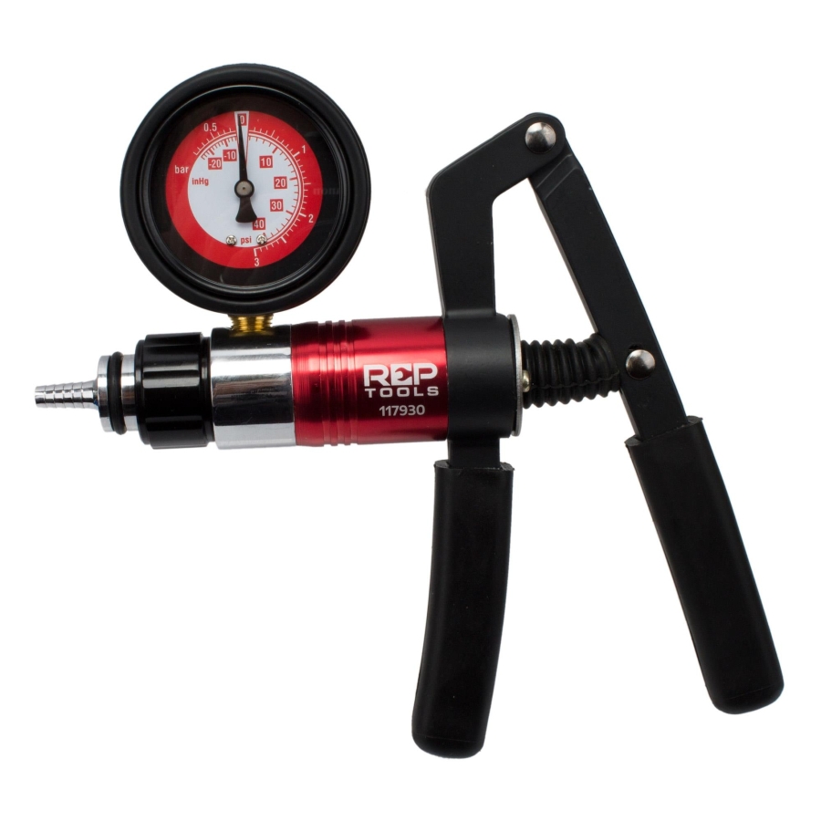
✔ Gauge range: -1 to +3 bar (vacuum & pressure)
✔ Dual-scale gauge (bar / PSI / inHg)
✔ Ideal for testing turbo, MAP sensors, valves, and vacuum systems
✔ Compatible with petrol and diesel engines
✔ item.no. kit suitable for professional workshop use
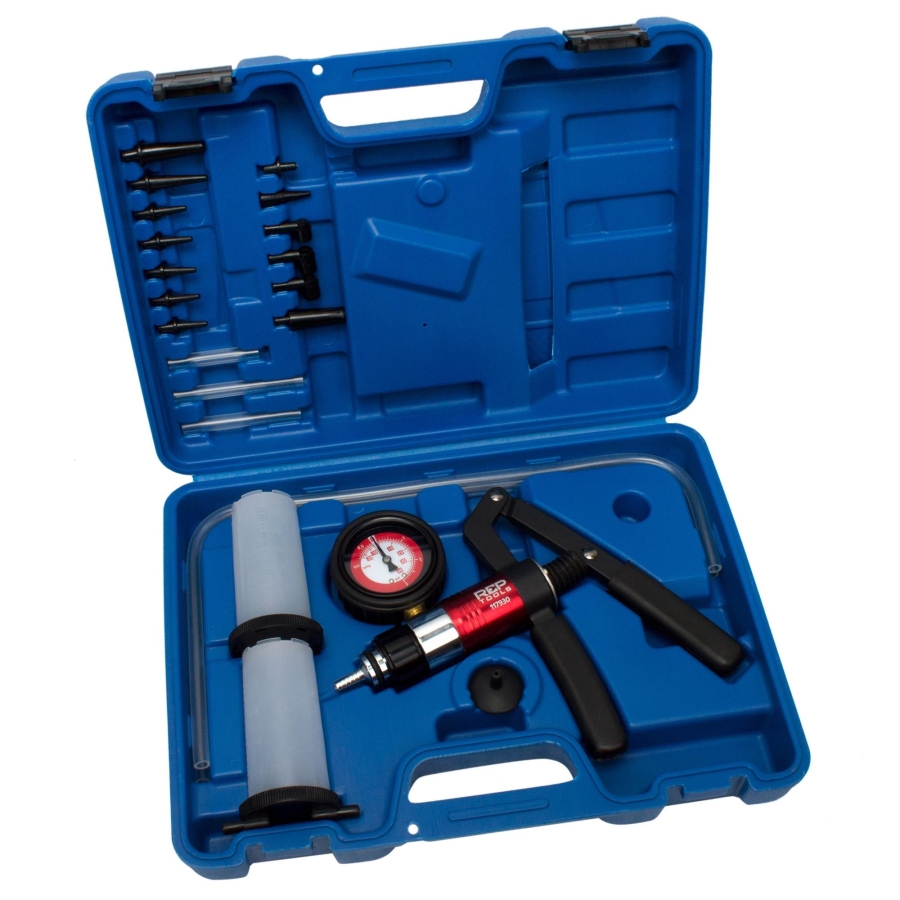
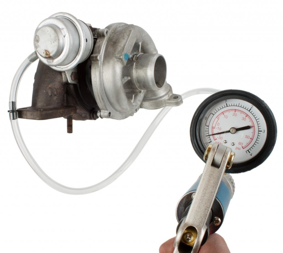
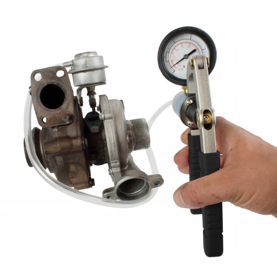
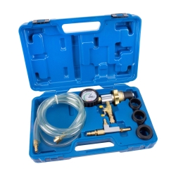
This vacuum and pressure pump kit is designed for comprehensive testing of vehicle systems and can also be used as a brake bleeding device using the included adapters and caps. It is an essential tool for maintaining engine performance and emission efficiency.
Wide Range of Automotive Applications
Suitable for testing and servicing multiple vehicle systems, including:
- Boost pressure systems
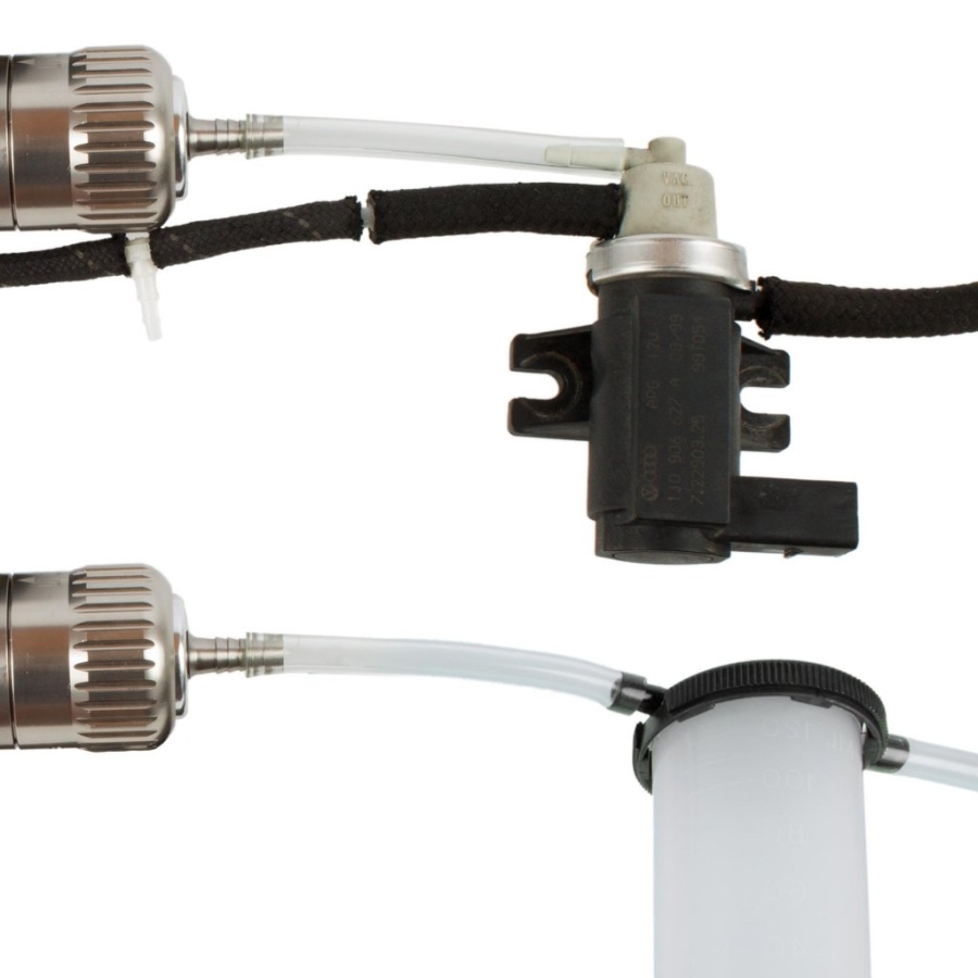
- Vacuum solenoid valves
- Fuel tank ventilation systems
- MAP sensors
- General vacuum and pressure-controlled components
The kit supports both petrol and diesel engines, making it universally applicable.
Precision Measurement with Dual-Scale Gauge
The factory-calibrated gauge ensures accurate readings across multiple units (bar, PSI, inHg), making it suitable for both European and imported vehicles.
Technical specifications:
- Gauge size: 63.5 mm
- Pressure range: 0 to +3 bar
- Vacuum range: 0 to -1 bar
- Max vacuum: -0.7 bar
- Max pressure: 3 bar
Essential Tool for Engine Performance Diagnostics
Since most internal combustion engines rely on vacuum systems for critical functions, this tool allows accurate diagnosis and maintenance of engine efficiency, drivability, and emissions performance.
| Qty | Product Name | Specification |
|---|---|---|
| 1 pc | Pressure/Vacuum Pump | Positive pressure: 0 – 4.1 bar (0 ~ 60 psi) Vacuum: up to -0.7 bar / -20 inHg |
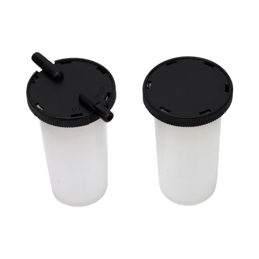
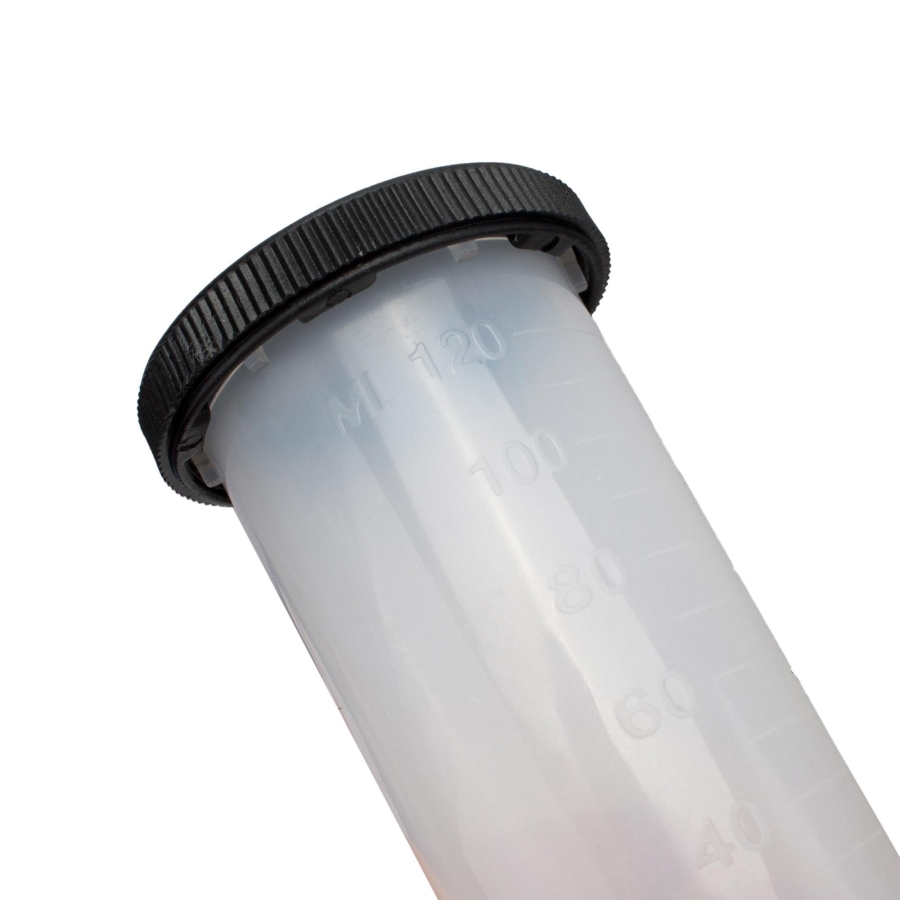
| 2 pcs | Reservoir with lid and inlet/outlet | Scale up to 120 ml |
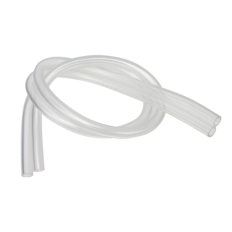
| 2 pcs | Hose | Length: 580 mm |
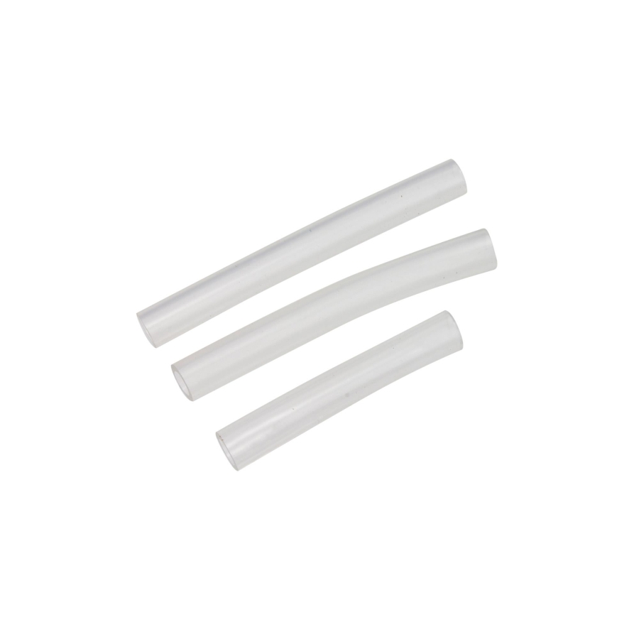
| 3 pcs | Hose | Length: 60, 75, and 90 mm |
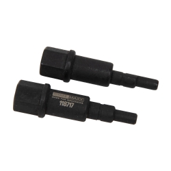
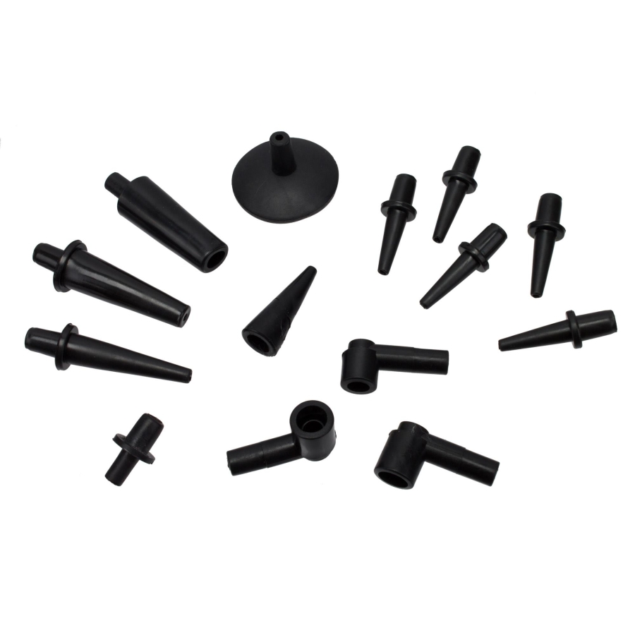
| 1 pc | Tapered adapter | 10 – 13 mm |
| 2 pcs | Tapered adapter | Ø 4 – 8 mm and 7 – 12 mm |
| 5 pcs | Tapered adapter | Ø 3 – 5 mm |
| 1 pc | Tapered adapter | Ø 5 – 7 mm |
| 3 pcs | Angle adapter | Connection Ø 6 and 7.5 mm |
| 1 pc | Tapered plug | Ø 3 – 10 mm |
| 1 pc | Suction cup with passage | Suction cup Ø 33 mm |
OEM Reference Compatibility
Suitable for use as Ford 416-D001, ensuring compatibility with manufacturer-specified diagnostic procedures.
OEM numbers are for identification purposes only and do not indicate original manufacturer tooling.
Bleeding Sequence
When bleeding the brake system, follow the vehicle manufacturer’s guidelines. In most cases, the procedure is as follows:
- Start with the wheel cylinder that is furthest from the master brake cylinder.
- Then bleed the second furthest, and so on.
- For left-hand drive vehicles, the typical sequence is:
rear right → rear left → front right → front left
Brake Bleeding Procedure
- Ensure that the brake fluid reservoir of the master cylinder is full and open.
- Connect the short plastic hose to the lid of the bleeding container and place the lid onto the container. The short hose must be inside the container.
- Connect the bleeding container to the hand vacuum pump using the other short hose.
- Connect one end of the long hose to the bleeding container and the other end to a suitable adapter for the brake caliper bleed valve.
- Check the brake fluid level in the reservoir before bleeding the next wheel cylinder or brake caliper.
- Attach the bleeding adapter to the bleed valve of the wheel cylinder or brake caliper.
- Pump 10–15 times until vacuum is generated.
-
Open the bleed valve until brake fluid flows through the hose without air bubbles.
Note: Steps 7–8 may need to be repeated several times.
- Important: Finally, check the brake fluid level and top up if necessary.
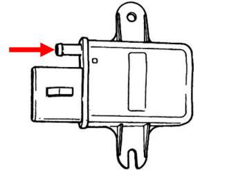
MAP Sensor Test (Example)
- Connect one end of the long plastic hose to the vacuum pump.
- Connect the other end of the hose to the test object, e.g. a MAP (Manifold Absolute Pressure) sensor.
- Operate the vacuum pump until a value is indicated.
- The value must not drop; otherwise, the MAP sensor has a leak and must be replaced.
-
Compare the output signal of the MAP sensor with the applied vacuum value.
Some vehicles use MAP sensors that output a frequency signal to the control unit. Depending on the applied vacuum, this signal typically ranges between 85 and 160 Hz.
Note: To verify the characteristic map, a frequency meter is required in addition to the vacuum pump. Manufacturer sensor data must be available for this test.
General Note
Listing all possible test procedures is not feasible due to the wide variety of vehicle types.
Refer to workshop manuals specific to your vehicle, which are available on the market, for additional testing procedures.