Automotive Voltage and Current Tester 1–48V
-
Code:8890
-
Weight:0.850 Kgs
Overview:
✔ Professional diagnostic tester for automotive electrical circuits
✔ Measures voltage from 1–48V DC with ±1% accuracy
✔ Measures current directly through fuse sockets up to 30A / 48V DC
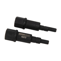
✔ Includes Mini and ATO fuse adapters for vehicle applications
✔ Large LCD display for quick and precise readings
✔ Complete testing kit with probes, crocodile clips and measurement cables
✔ Suitable for workshop diagnostics and automotive electrical troubleshooting

The Automotive Voltage and Current Tester 1–48V is a professional diagnostic tool designed for fast, precise, and safe electrical measurements in automotive systems. The unit allows voltage measurements from 1–48V DC and current measurements directly through the vehicle fuse socket using the supplied fuse adapter.
Its large LCD display ensures clear visibility during testing, while the included Mini and ATO fuse adapters allow quick connection to vehicle electrical circuits. The complete accessory kit makes the tester suitable for diagnostics, troubleshooting, and inspection of automotive electrical systems.
Ideal for workshops, technicians, and vehicle repair professionals.
Technical Specifications
- Voltage measuring range: 1–48V DC
- Voltage accuracy: ±1%
- Current measuring range: Max. 30A at 48V DC (maximum 10 seconds)
- Current accuracy: ±1%
- Current measurement method: Directly through fuse socket using fuse adapter
- Operating temperature: 0°C to 50°C
- Storage temperature: -20°C to 60°C
- Operating humidity: <70% RH
- Storage humidity: <80% RH
- Maximum operating altitude: 2000 m
- Power supply: 1 × 9V battery
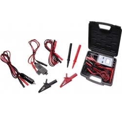
Package Contents
- 1 × Voltage and current tester
- 2 × Crocodile clips (1 red / 1 black)
- 1 × Voltage measuring cable with cigarette lighter connector, length 950 mm
- 1 × Current measuring cable with fuse adapter, length 600 mm
- 1 × Red measuring cable with insulated connectors on both ends, length 900 mm
- 1 × Black measuring cable with insulated connectors on both ends, length 900 mm
- 2 × Test probes (red / black) with 4 mm connectors and protective caps
Important Usage Information
- Current measurements can only be performed with the supplied fuse adapter connected.
- Always reinstall the original fuse or a fuse with the same rating into the fuse adapter to maintain circuit protection.
- Do not measure currents exceeding 30A or voltages exceeding 48V.
- After measurements at maximum values (30A or 48V), allow the device to cool for at least 10 seconds before continued use.
- Fuses may become hot during prolonged measurements; allow sufficient cooling before removal.
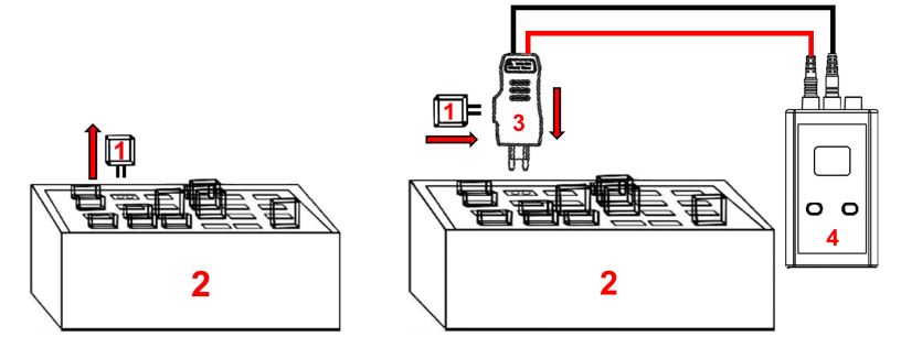
Direct Current Measurement
- Switch off the vehicle ignition. Connect the measuring device as shown in the illustration.
- Remove the fuse (1) of the circuit to be measured from the fuse box (2) and insert this fuse (1) into the fuse adapter (3).
- Insert the fuse adapter (3) into the fuse socket of the circuit to be measured. The vehicle can now be started if necessary.
Note: Current measurement can only be performed using the fuse adapter.
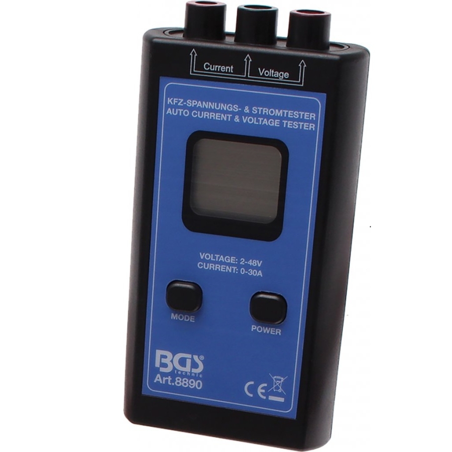
- Press the "POWER" button to switch on the measuring device (4).
- Press the "MODE" button to select Current Measurement mode. The letter "A" will appear on the LCD display.
- The measured value can now be read from the display.
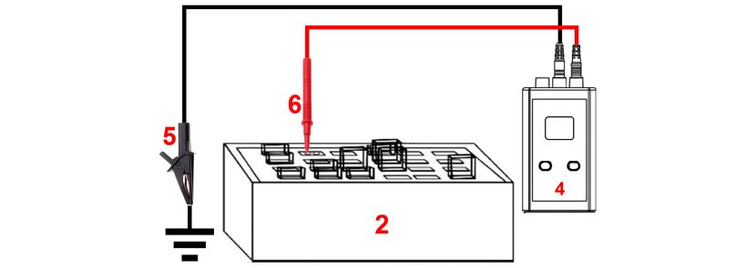
DC Voltage Measurement
- Switch off the vehicle ignition.
- Connect the red test lead to the tester and the test probe (6).
- Connect the black test lead to the tester and the crocodile clip.
- Attach the crocodile clip to a suitable ground point (ground cable, screw, etc.).
- Press the "POWER" button to switch on the measuring device (4).
- Press the "MODE" button to select Voltage Measurement mode. The letter "V" will appear on the LCD display.
- Measurement with the test probe (6) can now begin. The example shown illustrates a voltage measurement at a fuse socket.
- If the measured voltage is below 1 V, no value will be displayed.
- If the polarity is incorrect during measurement, the display will show "ERR" and the buzzer will sound. Reverse the test lead connections and repeat the measurement.
Continuity Measurement
- Switch off the vehicle ignition.
- Connect the red test lead to the tester and the red crocodile clip.
- Connect the black test lead to the tester and the black crocodile clip.
- Press the "POWER" button to switch on the device.
- Press the "MODE" button to select Continuity Measurement mode.
- The continuity test can now begin using the crocodile clips. Attach the electrical terminals of the component to be tested to the two crocodile clips.
- If the measured resistance is below 1 kΩ, "ERR" will be displayed and the buzzer will sound. This indicates that the component has continuity.